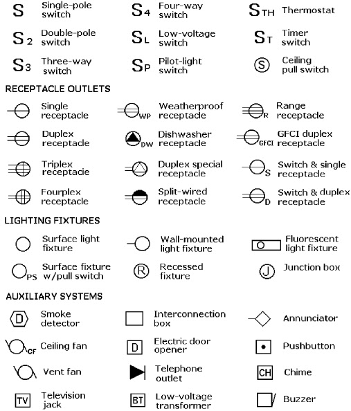
Ever glanced at a blueprint and felt a little lost in the sea of lines, symbols, and abbreviations? You're not alone. Blueprints are a complex language, and understanding them is crucial for any construction or renovation project. One common element that often causes confusion is the representation of light switches. This seemingly small detail plays a significant role in the overall electrical layout of a building.
Understanding light switch representations on blueprints isn't just about knowing where a switch goes; it's about understanding the entire electrical circuitry connected to it. It impacts how electricians wire the building, how the lighting functions, and even the overall energy efficiency of the space. This article will illuminate the world of light switch symbols on blueprints, providing a comprehensive guide to their interpretation and implementation.
From simple single-pole switches to more complex three-way and four-way configurations, the symbols used on blueprints convey a wealth of information. These symbols are standardized to ensure clear communication between architects, engineers, electricians, and contractors. Learning to decipher these symbols is like unlocking a secret code to understanding the electrical soul of a building.
The history of these symbols is intertwined with the development of electrical systems themselves. As electricity became commonplace in buildings, the need for a standardized visual language arose. Over time, these symbols evolved, becoming more refined and encompassing a wider range of switch types and functionalities. This standardization is critical for preventing errors during construction and ensuring the safety and functionality of the electrical system.
Navigating the complexities of electrical blueprints can be daunting, especially when encountering unfamiliar symbols. But the importance of accurate interpretation cannot be overstated. Misinterpreting a symbol can lead to costly mistakes, requiring rewiring and potentially delaying the project. A deep dive into the meaning of these symbols is essential for anyone involved in the design, construction, or renovation of a building.
A standard single-pole switch is represented by a simple "S" on the blueprint. A three-way switch, which allows control of a light from two locations, is typically represented by an "S" with two small lines extending from it. A four-way switch, allowing control from three or more locations, uses a similar symbol but with three lines. These standardized symbols allow for quick and easy identification of switch types on the blueprint.
Three key benefits of understanding these symbols are efficient communication, accurate installation, and cost savings. Clear communication ensures that everyone involved in the project is on the same page. Accurate installation prevents costly mistakes and rework. And understanding the electrical layout upfront can lead to better planning and potential cost savings during the construction process.
Advantages and Disadvantages of Standardized Symbols
| Advantages | Disadvantages |
|---|---|
| Clear communication | Requires learning the symbols |
| Reduced errors | Variations can exist between different standards |
| Improved safety |
Best practices for working with light switch symbols include consulting the blueprint legend, cross-referencing with the electrical specifications, and seeking clarification from the architect or engineer if any uncertainties arise.
Real-world examples of light switch symbols can be found in any architectural or electrical blueprint. Look for residential, commercial, and industrial blueprints to see how these symbols are applied in different contexts.
A common challenge is encountering variations in symbols used on older or international blueprints. The solution is to always refer to the blueprint legend, which provides a key to all symbols used.
FAQ:
Q: What does an "S3" on a blueprint mean?
A: It typically represents a three-way switch.
Q: Where can I find a comprehensive guide to blueprint symbols?
A: Many architectural and electrical handbooks provide detailed explanations of blueprint symbols.
Q: What does a dimmed light symbol represent?
A: It indicates a light fixture controlled by a dimmer switch.
Q: How are switches connected to circuits on blueprints?
A: Lines are used to connect switches to their respective circuits.
Q: Are there different symbols for different types of light switches?
A: Yes, the symbols vary depending on the type of switch (single-pole, three-way, four-way, dimmer, etc.).
Q: What is the symbol for a switch with a pilot light?
A: It often includes a small dot or triangle within the switch symbol.
Q: How are exterior lights represented on blueprints?
A: They usually have a distinct symbol, often including a weatherproof designation.
Q: What is the symbol for a switched outlet?
A: It usually combines the outlet symbol with a switch symbol.
Tips and tricks: Always consult the blueprint legend, use a ruler to measure distances accurately, and double-check your interpretations to avoid mistakes.
Understanding light switch symbols on blueprints is essential for anyone involved in the construction or renovation process. These symbols are a critical part of the blueprint language, conveying vital information about the electrical system. From simple single-pole switches to complex multi-way configurations, being able to interpret these symbols accurately is key to a successful project. This understanding not only ensures proper functionality but also helps prevent costly errors and rework. By familiarizing yourself with these symbols, you’ll be well-equipped to navigate the complexities of blueprints and contribute to a smoother, more efficient building process. Take the time to learn this crucial aspect of blueprint reading, and you'll empower yourself with the knowledge to bring your building plans to light. Remember to always consult the blueprint legend for clarification and seek expert advice when needed. By mastering this skill, you are taking a significant step towards ensuring the safe and effective implementation of your electrical systems.
Leveling the playing field exploring the notion of equality of condition
Unlocking yukikos potential a persona 4 golden guide
Upgrade your shower brilliant tile shower bench ideas


