Ever looked at a circuit diagram and felt lost in a maze of lines and squiggles? Understanding electrical schematic symbols is the key to unlocking this complex world. These symbols, a standardized visual language, are the building blocks of every electrical design, from simple household wiring to intricate industrial control systems.
Imagine trying to build a house without understanding blueprints. Similarly, electrical schematics, populated with these standardized symbols, serve as the blueprints for electrical circuits. They provide a concise and universally understood representation of circuit components and their interconnections, enabling engineers, technicians, and hobbyists to design, analyze, and troubleshoot electrical systems effectively.
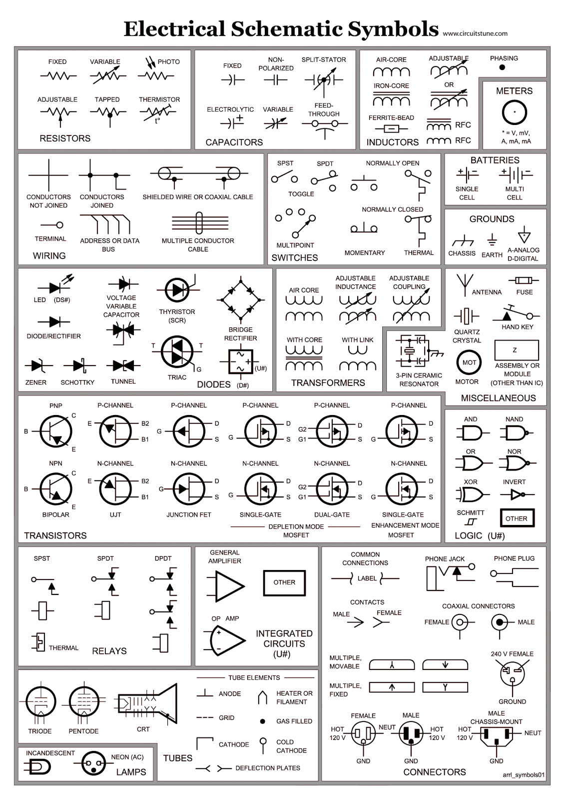
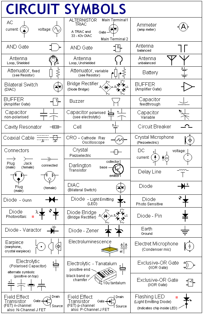
Finding a comprehensive guide to these symbols, often compiled in a "basic electrical schematic symbols PDF," is a crucial first step for anyone venturing into the realm of electronics. These PDFs offer a readily accessible and portable reference, containing a library of symbols representing various components like resistors, capacitors, transistors, and switches. Knowing where to locate and how to interpret these documents is paramount.
The use of standardized electrical symbols has a rich history, evolving alongside the development of electrical technology itself. Early schematics were often hand-drawn and lacked uniformity, leading to potential confusion and misinterpretations. The increasing complexity of electrical systems necessitated the establishment of standardized representations, leading to the creation of organizations like the IEEE (Institute of Electrical and Electronics Engineers) that play a vital role in defining and maintaining these standards.
A readily available compilation, like a "basic electrical symbols chart PDF," can be an invaluable resource for both beginners and experienced professionals. It provides a quick reference guide, allowing for efficient identification of components within a circuit diagram. Such resources also often include information on the function and properties of each component, further enhancing understanding.
One key issue related to these resources is ensuring their accuracy and adherence to current standards. Using outdated or inaccurate symbols can lead to design errors and safety hazards. Therefore, it's crucial to rely on reputable sources for these diagrams and PDF guides.
A resistor, for example, is represented by a zig-zag line. This simple symbol conveys a wealth of information to someone familiar with electrical schematics, indicating the presence of a component that restricts the flow of current. Similarly, a capacitor is represented by two parallel lines, signifying its ability to store electrical charge.
One benefit of using standard symbols is improved communication. Engineers across the globe can readily understand a schematic regardless of language barriers. This universality facilitates collaboration and knowledge sharing within the electrical engineering community.
Another advantage is enhanced troubleshooting. By understanding the symbols and how they interact within the circuit, technicians can quickly pinpoint faulty components and rectify issues. This speeds up repairs and minimizes downtime.
Finally, using standard schematic symbols aids in efficient circuit design. The clear and concise representation allows engineers to visualize the circuit's operation and optimize its performance before physical implementation.
Advantages and Disadvantages of using Basic Electrical Schematic Symbols PDF
| Advantages | Disadvantages |
|---|---|
| Easy access and portability | Potential for outdated information |
| Comprehensive reference | Requires basic understanding of symbols |
| Aids in learning and understanding | May not cover all specialized symbols |
Finding a reliable and up-to-date "electrical schematic symbols PDF download" is the first step in your learning journey. Numerous online resources and educational websites offer free downloads of these PDFs, ensuring easy access to this essential information. Combine this with practical experimentation and circuit building for a well-rounded understanding.
Understanding electrical schematic symbols is fundamental to anyone working with or studying electronics. These symbols, readily available in PDF format, are the key to deciphering the language of circuits. By mastering these visual cues, you unlock the ability to design, analyze, and troubleshoot electrical systems effectively. Invest time in learning these symbols and exploring the wealth of resources available, and embark on a rewarding journey into the world of electronics.
Rainbow barn paint grey a colorful twist on rustic charm
The sss level paladin transcending conventional wisdom
The allure of pink aesthetic laptop wallpapers a journey through digital aesthetics


.jpg)


